ESP32 Solar Camera Project
In general I've been moving away from only building complex/technically-flashy things in my spare time and just trying to build things which are neat, even if they are simple. This is to help me avoid burnout, and quell impulses of perfectionism which tend to monopolize my time.
I'd been doing a bit of reading about solar panels and wanted to build something solar-powered. Particularly with my recent low-power ESP32 escapades, I was ready to do something in that vein. I got to work planning and prototyping with a goal of building a thingy which would collect solar energy, periodically taking a photo and uploading it somewhere.
This all ended up taking far longer than I expected it to.
First Attempt
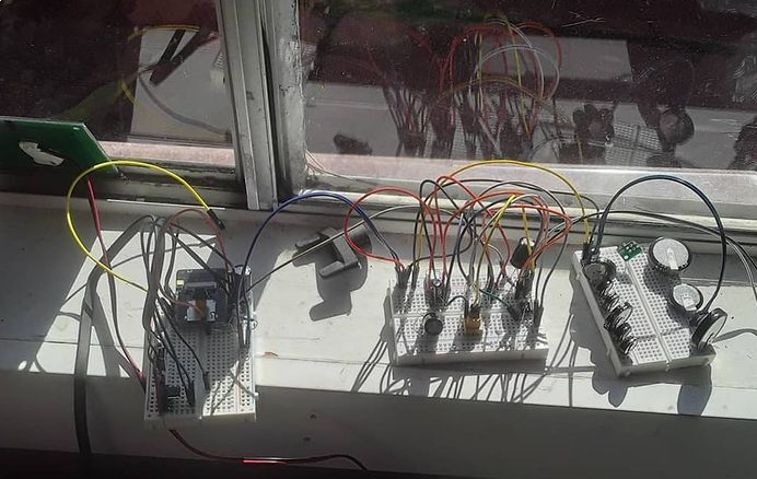
I started by drawing things in CircuitLab and playing with breadboards. I desired to use a 2.5ish V solar panel I harvested from a yard lantern. I figured that with a boost converter, I could take whatever this panel was putting out up to 5V and use that to charge a supercapacitor. Then I could take another boost converter and use that to power my ESP32-CAM module and boom! Job done! Or...not.
Supercapacitor Charging
First off, you can't just hook a boost converter to a supercapacitor; the supercapacitor has very low impedance and, when it's empty, will effectively 'short out' the boost converter. So you need some kind of current limiting. No problem there - I can just make such thing with an opamp and a reasonably chunky MOSFET. So I did that and, after some messing around, I managed to charge a supercapacitor at a current-limited rate, up to 5V, using a low voltage solar panel. Hurrah!
UVLO
I also needed an undervoltage lockout circuit or UVLO - this circuit avoids powering the ESP32 until some voltage threshold is reached by the supercapacitor. A UVLO then only switches off when a (lower) off-threshold is crossed.
It's needed because the ESP32 sucks quite a lot of power on startup, and if it were allowed to turn on as soon as the boost converter sensed enough supercap charge to start, it would immediately:
- Suck a lot of current out of the supercap
- The supercap voltage would drop too low for the boost converter to operate
- The boost converter would stop working and stop drawing current
- The supercap voltage would go high enough to start the boost converter
- Start all over again
This would repeat over and over and make no progress. No problem! The hysteresis portion of the UVLO can be implemented with an op-amp and positive feedback network, and I already have a dual op-amp chip in the design from the current limiter, so I can use the other op-amp in there with another MOSFET, to implement a UVLO. This also seemed to work, after a little tweaking.
I got a bit carried away
This is where things took a turn for the complicated. I didn't like having 2 boost converters in a design when theoretically, the services of only one should be enough. So I got to designing a circuit that would share the input to the boost converter between the solar input, and the supercap's charge, and would use that boosted output to power the ESP32, and also charge the supercap further when appropriate. It was a neat design and...I basically just couldn't get it working enough.
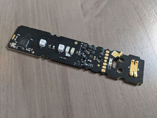
I even designed/ordered a PCB with all of the above, partially because I just wanted to make a PCB for the first time in a while, but also because I really thought it would work.
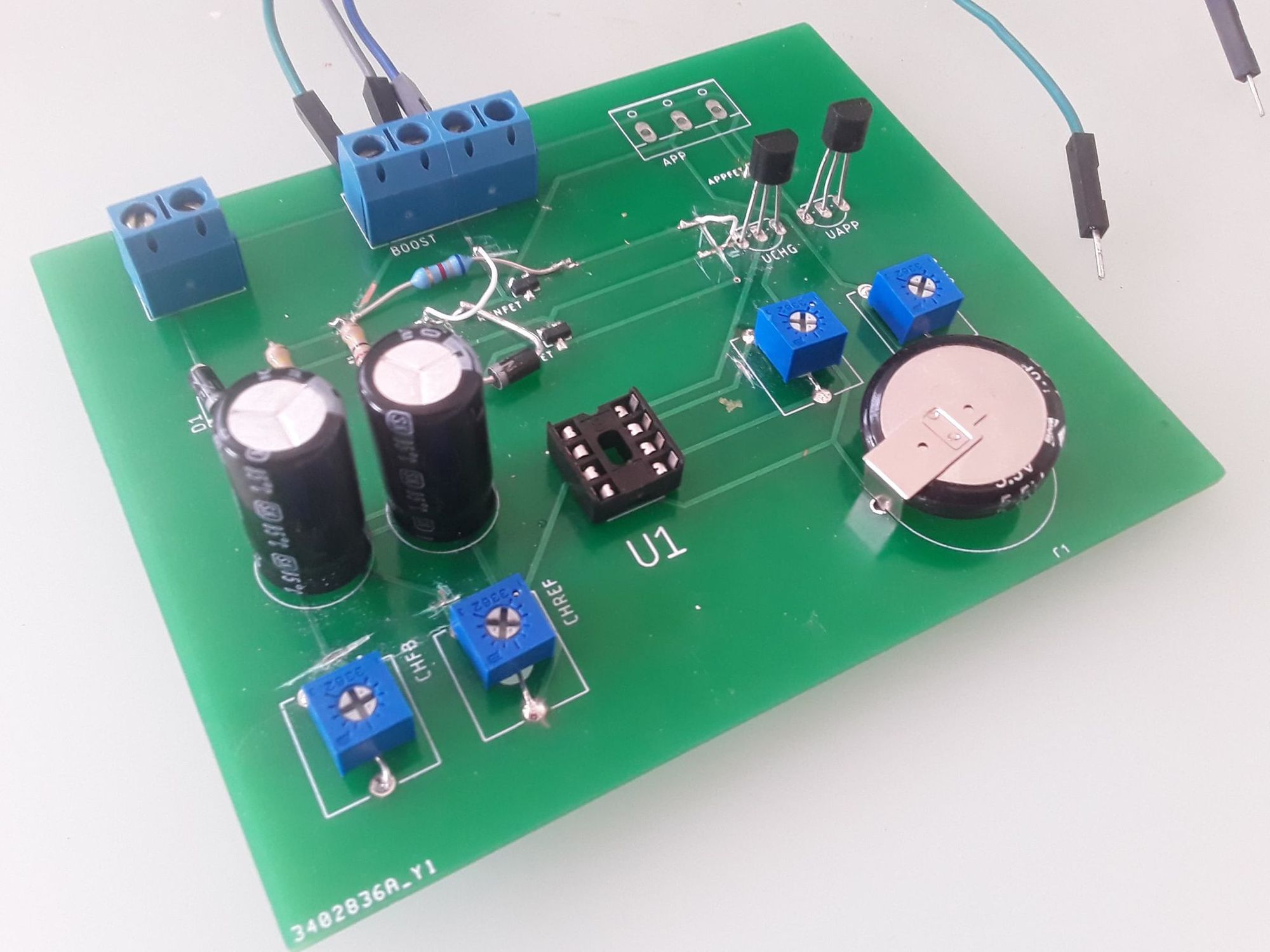
There were multiple issues. One of the main ones being that the boost converter kept oscillating when the supercap charge got too low. I took measurements, experimented, asked on IRC and learned a bit more boost converters (A good article https://www.eetimes.com/power-tip-3-damping-the-input-filter-part-1/#), and it turns out that having a small supply impedance is crucial to not accidentally making an oscillator here. I also learned that the supercaps I was using were quite low quality and had high equivalent series resistance (ESR), meaning that the input to the boost converter was wobbling all over the place. Notice in the picture above how I have a bunch of them paralleled.
Second attempt
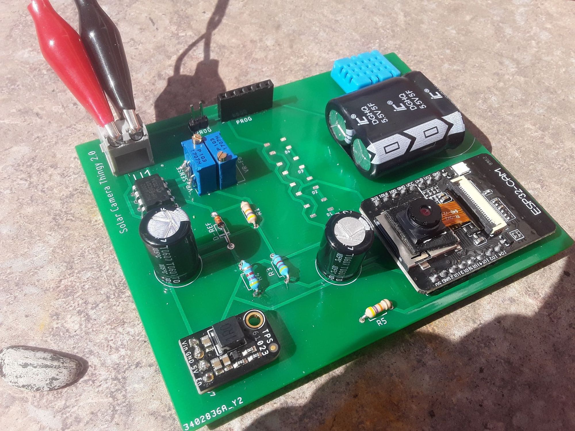
So after lots of lessons learned I canned that particular design and set about simplifying it all, while also filling in some gaps I left in the previous one. This time, I didn't bother trying to do the boost-converter sharing thing. Instead, I used a higher voltage solar panel (5v), which I could connect to the supercap directly. I still need a UVLO to power on/off the ESP32, but nothing more fancy than that.
Rather than working with the supercaps I had, I did some searching around and acquired some much nicer ones, with much lower ESR (https://www.newark.com/illinois-capacitor/dgh505q5r5/supercap-5f-5-5v-radial/dp/16AC9334). I only needed 1 in the end!
Some New Features
- Programming header/jumper
- Area to mount the actual ESP32 & boost converter
- Space for WS2812 LEDs
- Space for DHT-11 temperature/humidity sensor
- Voltage divider for charge level sensing
This all worked pretty well!
Software
My plan is to not rely on the UVLO during normal operation - while the sun is somewhat out, the ESP32 should try to stay running, checking the supercap charge level and collecting temperature/humidity data, even if there's not enough power to connect to Wifi and upload an image (by far the most power-expensive thing this circuit does).
The ESP32 features a 'deep sleep' mode which shuts down most of the microcontroller, leaving the realtime clock and a small amount of RAM running, so it can wake back up based on a timer or other triggers. See here for more info: https://lastminuteengineers.com/esp32-deep-sleep-wakeup-sources/.
Sleep Algorithm
I played with a bunch of strategies for saving power, but ended up going for the following:
There's a fixed "wifi threshold" - 4.4V. If the ESP32 reads this or higher voltage at startup, it'll try to take a picture and upload it over wifi. If not, it will log data, go to sleep for a bit then try again.
As for how long to sleep, we try 2-minute "short sleeps" for as long as the voltage always appears to be increasing (or staying above wifi threshold) between wakeups.
If the voltage is observed to drop during a short sleep, that means the power cost of waking the ESP32 is outstripping what power the solar panel can provide during a short sleep.
In this case, we switch to 30-minute "long sleeps", staying in this "long sleep" mode until the wifi threshold is reached again. Once the wifi threshold is reached, we go back to trying short sleeps as above.
Data Logging
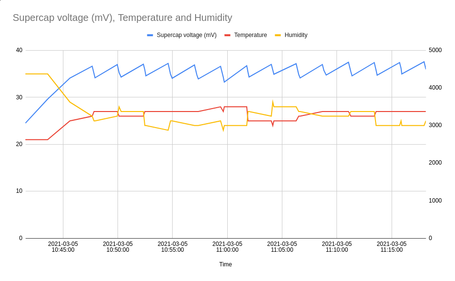
Making use of the RTC and the RAM which persists through deep sleeps I decided to log the supercap voltage, as well as temperature and humidity from the DHT-11 sensor on every startup, regardless of whether there is enough power for wifi.
Then at the next wifi connection, we upload all of the previously logged data.
Cameras are hard
So it's all working apart from one small detail; the camera is doing ALL KINDS of wacky stuff. I went through various strange failure/glitch modes.
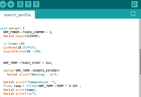
Greenness
At one point, the camera would produce green-tinted images. I went down various rabbit holes suspecting electrical issues, a faulty SPI RAM chip, etc... It turned out to be very straightforward - the camera needs some number of frames to 'warm up' and get its automatic gain control into a good place, and I wasn't giving it that because I was uploading the first frame that came out of it. Makes sense when you think about it!
Timeouts
These OV2640 camera modules seem to be a bit unreliable - both of the ones I have don't always initialize the first time, and sometimes don't produce a frame. Some googling indicates this isn't completely unknown, and my solution is to basically retry a bunch of times, before giving up and going to sleep again.
Frame Corruption
So here's a weird one. I noticed that if the sun moves into frame (or just seemingly randomly at other points), i'd end up getting half a picture; eg:
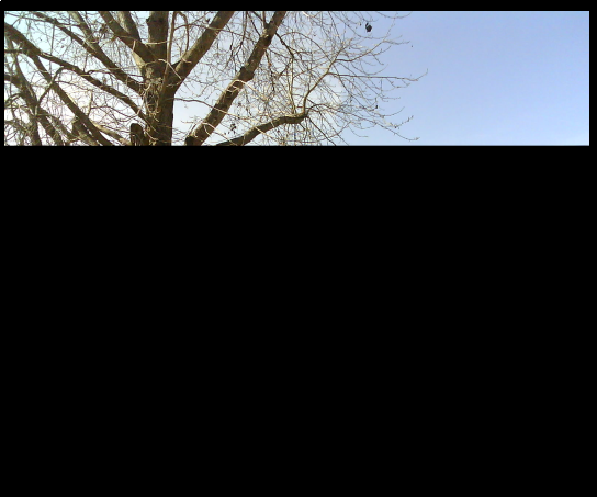
After much googling, headscratching, playing with registers in the camera and reading the OV2640 Reference Manual, I have a theory about what causes this. The clock architecture is thus:
- The camera's 'main clock' (XVCLK) is generated by the ESP32 (default 20MHz).
- XVCLK is divided by the CLKRC register to generate the pixel/frame clocks internally.
- This resulting clock is further converted via PLL/divider (R_DVP_SP) to PCLK, which is then used to clock data out of the camera and into the ESP32.
So, reducing CLKRC makes the framerate increase, and reducing R_DVP_SP makes the data rate increase. However! One cannot simply reduce R_DVP_SP to its lowest possible value, as it will be shifting data out faster than the I2S peripheral in the ESP32 can consume it. Now, the amount of (JPEG) data to shift out depends on how much the image can be compressed. So I suspect the above happens when there's not enough time to shift out all of the data before the next frame starts. But I haven't confirmed this.
My solution has been to reduce the framerate (via CLKRC), then increase the PCLK (via R_DVP_SP) up to the maximum the ESP32 will tolerate. Leaving more time to get all the data out before the next frame starts.
Tools
CircuitLab
Eagle PCB

ESP32-CAM

ESP-IDF
 espressif
esp32-camera
espressif