BLE Covid Test #3: Bringing it all together!
So here's what is likely the final installment in my COVID test explorations. I've learned a bunch and got some seemingly useful practical experience.
Broadly, I knew where I wanted to go with this - I wanted to be able to use the Arduino IDE to reprogram the device, and I wanted to be able to make use of the BLE radio to do something interesting. In my last post, I talked about getting the Jeff Probe working with the nRF52810 chip, well enough that I could erase/program it.
I've not done much with the Arduino platform, so I knew I had to learn a bunch of little pieces on the way. The first thing I needed was an Arduino 'core' for this chip. This is Arduino parlance for a board support package, which implements what you might call the Arduino basics - initialization, serial ports, GPIO, ADC and the like. Some googling around led me pretty quickly to an nRF5x core:
 sandeepmistry
While it has no specific support for the nRF52810 chip, it has support for others which vary in relatively minor ways such as memory size, pinout and how many of whatever peripheral type there are. This also has Blackmagicprobe support which ended up working out-of-the-box with the Jeff Probe. So I set about creating a new board in boards.txt for the Ellume COVID test, along with an appropriately configured variant placed in the variants directory. A smattering of other little changes here and there were needed to get things going, including adding linker scripts and #ifdef directives. Without too much difficulty, I was able to write a program, compile it and download it onto the chip. I could even use gdb to verify that it was running!
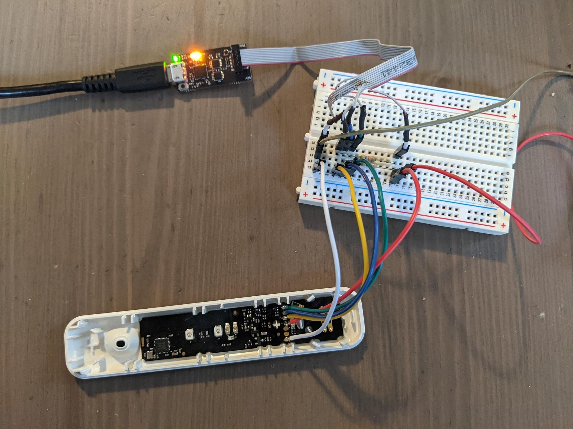
Something I needed to do at this point was figure out what GPIOs are hooked to what things on the board. From poking around with a multimeter and experimenting with some basic code, I gleaned the following:
- P0.18 - Green LED
- P0.15 - Red test strip-reading LEDs
- P0.12 - ??? - Driving it low while P0.15 is high makes one of the red LEDs turn off
- P0.25 - Something button-related
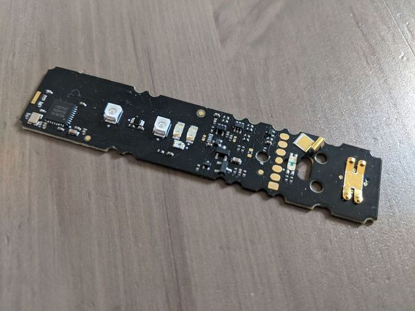
On P0.25/Button, I spent a lot of time poking around trying to figure out how exactly it worked. It wasn't trivial, and I was prodding it with an oscilloscope probe for quite a long time indeed, as it jumped around on pushing the button - a capacitor seemed to be involved. I prodded a little too hard however, so much so that I actually deformed the solder and shorted out that pin of the MCU 😱.
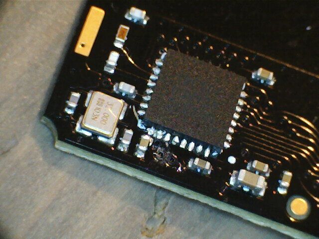
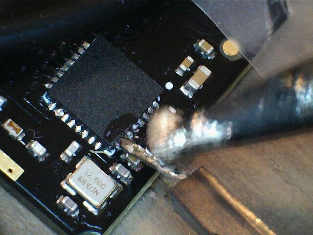
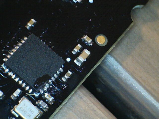
The bridge between those two bits of solder on the bottom-left of the chip is reasonably visible in the first pic. The second pic shows me trying to separate them indirectly, via a rigid pin - you can see the pesky capacitor preventing direct access with the soldering iron. The third picture shows what appears to be the once-again separated conductors.
Unfortunately after all of this poking and prodding, it still didn't work! Perhaps I left a dry joint under the QFN; more likely I feel is that my shorting out with VDD, combined with driving the pin low from software while I was experimenting, lead to that GPIO driver being permanently destroyed. Or maybe something else was wrong - who knows? In any case, I gave up on using the switch for anything and just moved on.
I also ended up figuring out those two unknown pads on the programming header!
- P0.16 - Pad 3 on the programming header
- P0.20 - Pad 2 on the programming header, and also a red LED
I decided these should be a UART, and pretty arbitrarily declared Pad 3 to be TX and Pad 2 to be RX; this has the nice benefit of making the red LED blink while data is being received.
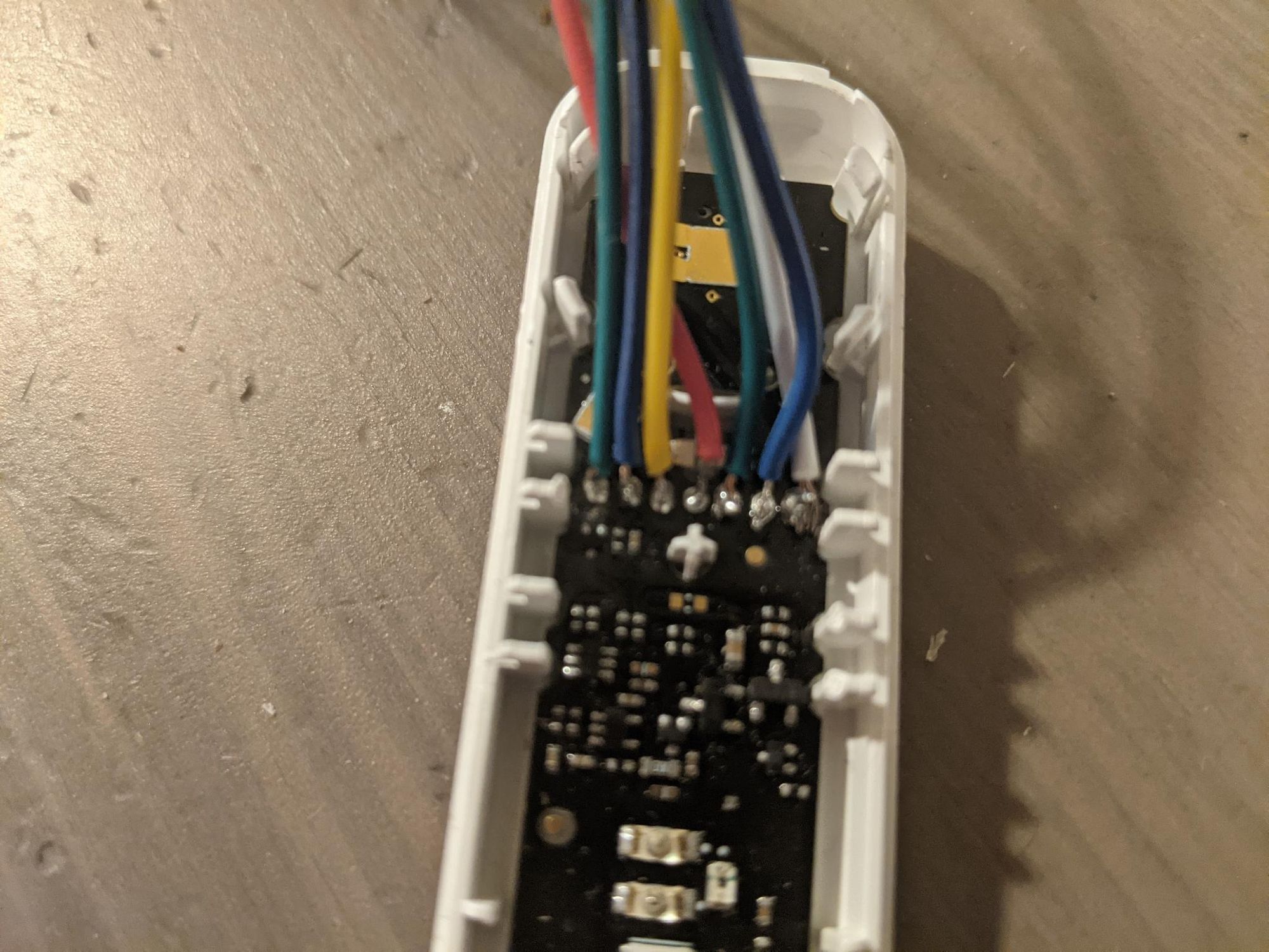
I wired these up to the TDI and TDO pins of the Jeff Probe; these aren't used when speaking SW-DP protocol, but the Blackmagic probe has a handy feature where you can set the lines to be logically attached to the second tty device presented by the probe, giving you a serial console. This behavior can be switched on in GDB via the command: monitor convert_tdio enable .
This was all working pretty well thus far, but of course still no BLE. I had a feeling this would be tough to get working and I was right, but not for any reason that I predicted.
BluefruitLib
To make things easier for myself I tried to find some Arduino-friendly way to do this. I figured I already have a working Arduino core, so this should just drop right in, right? Well kinda, but also no. Adafruit has a BluefruitLib library that seems to be super easy to use and even had some examples:
adafruitBut some digging around revealed that I couldn't just copy/paste that library into the Arduino core I was working with. This is because the library depends on the Adafruit core specifically, which is quite different from the one I have been working with and ported to the nRF52810. While being Arduinoish, it's actually based on FreeRTOS; BluefruitLib and its dependencies depend on the specifics of this core, and some FreeRTOS parts, in order to work.
Take 1
So I investigated trying to pull BluefruitLib and its dependencies out one-by-one, along with FreeRTOS. This was not as painful as one might fear, but it was quite painful. One problem was that this port of FreeRTOS seems to require hard floating point support - something the nRF52810 doesn't have. So I tried to mess with the context switching function, to avoid switching out FP registers, and hopefully make it compatible. In the end there was just a bunch of this kind of nonsense to get something basic building, and the result didn't even work! 😢 🗑️
Take 2
I mostly threw that monstrosity away and tried a different monstrosity approach, this time starting with the new Adafruit core for which BluefruitLib and its dependencies was designed. I had a pretty good understanding of how an Arduino core hung together at this point, and figured it wouldn't be terribly hard to port the Adafruit core (for the most part) to the nRF52810, remove the bits of FreeRTOS that didn't work for me and just try to kludge it into working in some minimal way. I did this work and actually got something building, downloaded and running! The UART was funky, but I figured I could sort that out. The biggest problem was when I tried to do anything with Bluetooth, BluefruitLib and all its friends would get pulled in as dependencies. The poor nRF52810 has a lot less memory than what these components are normally running on, so it didn't fit! 😭
I tried hacking bits off, to no avail. And yeah, the UART didn't work. 🗑️
Take 3
So my next attempt and the one that ultimately worked, was to go back to my original core, dispensing with BluefruitLib, FreeRTOS et al, and basically do the bluetooth interaction from scratch, ripping the necessary parts out of BluefruitLib. I only wanted a BLE beacon; I didn't even want connections/pairing, so that's a pretty small amount of functionality, I thought.
WTF is a Softdevice?
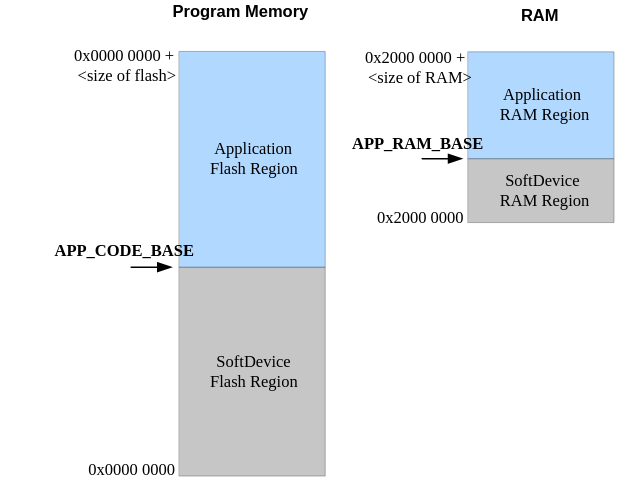
Thus far, I had been mainly running only the code in the Arduino core. I've not been using any bootloader etc; just writing my program directly into the MCU's flash at an appropriate address, so it's the first thing to run at powerup. This is fine and reasonable until you want to use BLE. It seems to be a universal constant that the presence of wireless hardware necessitates a binary blob. For Nordic's nRF52 devices, this blob is called a "Softdevice".
You use it by writing it into the flash where you would normally write your application, so it has control of the MCU on power up. It then acts a bit like a hypervisor - after doing some initialization itself, it jumps to the code located immediately after itself in flash (your application goes here) in exactly the way the CPU would do at power up; specifically, it expects to find an ARM interrupt vector table at that location, and jumps to the reset vector therein.
So you have this softdevice written into the lower chunk of flash, and your application, with its vector table, needs to be loaded immediately above it. This APP_CODE_BASE address is always immediately after the end of the softdevice blob (modulo some alignment), so the version of softdevice blob installed actually needs to match the sizes/offsets in the application's linker script; such a linker script will contain a memory layout like this:
MEMORY
{
  FLASH (rx) : ORIGIN = 0x26000, LENGTH = 0x30000 - 0x26000
  RAM (rwx)  : ORIGIN = 0x20003600, LENGTH = 0x20006000 - 0x20003600
}A corollary of this setup is that the softdevice gets first dibs on any interrupts; it can handle an interrupt itself or (normally) it can forward it to the application's vector table. Your application can access the hardware directly as usual, but it needs to ask the softdevice blob to do BLE work. Your application also needs to avoid touching RTC0, which the softdevice expects to have exclusive access to. There is an API to call various functions of the softdevice, which seems to be implemented using software interrupts.
SO! As part of my "Take 3" I also needed to upgrade the softdevice version (and API headers) to match the version (v6.1.1) used in the Adafruit code I was callously ripping out of BluefruitLib, to ensure it would work properly with minimal adjustment.
Success!
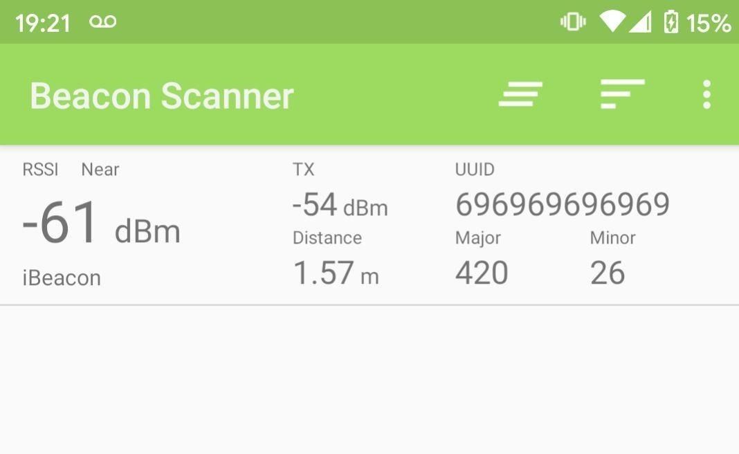
After a whole lot of mashing sourcecode around into the right shape, I got everything into a function that's needed to initialize a beacon that broadcasts for 3 seconds.
routevegetableMoreover, what I ended up doing for this project was read the internal temperature sensor of the MCU and include that reading in the minor number of the beacon. Not particularly big or clever, but undeniably satisfying and it actually seems pretty accurate as far as I can tell.
IRQs/SoftDevice Events
The softdevice pretty much completely handles the transmission, signalling the user application that it has run for the desired time, via an "SD Event":
SD Events are delivered to the application via a interrupt; or rather, your application receives an interrupt when there are events to read from the softdevice. Such a handler in your application might look like this:
extern "C" void SD_EVT_IRQHandler(void)
{
  got_sd_events = true;
}
The application's main loop can then periodically check this flag and, if it is set, retrieve any pending events via a softdevice call. The code could look like this:
if(got_sd_events)
{
    got_sd_events = false;

    // For each pending event:
    bool done = false;
    while(!done)
    {
        // Get BLE event from softdevice
        uint32_t err = sd_ble_evt_get(ev_buf, &ev_len);

        switch (err) {
        case NRF_SUCCESS:
            /* ... Handle event ... */
            break;
        case NRF_ERROR_NOT_FOUND:
            /* ... Done processing all events */
            done = true;
            break;
        default:
            /* Some kind of error! */
            done = true;
            break;
        }
    }
}
Sleeping
This is an area where my inexperience with the nRF52 shows. I was expecting to find something akin to the ESP32's model of deep sleep, light sleep, etc... I found this isn't exactly the case - the nRF52 is just a way less power-hungry chip. To get decent power usage, you can just...stop doing things. Sitting in a loop or on a wfi instruction, with the automatic low power mode enabled (simply NRF_POWER->LOWPWR = 1;) gets the chip down into the range of 10s of microamps. The datasheet suggests much more power saving is possible, down to sub-microamp amounts by disabling peripherals, clocks and RAM retention, but my lack of patience got the better of me and I just wanted to see it do some stuff. So I made a very much belt-and-braces implementation of 'do a thing, sleep for 30 seconds, do it again, and so on...'. From power-on, I do 3 seconds of beacon-transmitting, then I embark upon the following litany of crazed off-switch-throwing:
Serial.end();
// Disable softdevice
sd_softdevice_disable();

// Kill RTC interrupt for better quality sleep
NVIC_DisableIRQ(RTC1_IRQn);

// Kill timers?
NRF_TIMER0->TASKS_STOP = 1;
NRF_TIMER1->TASKS_STOP = 1;
NRF_TIMER2->TASKS_STOP = 1;

// Kill RTCs?
NRF_RTC0->TASKS_STOP = 1;
NRF_RTC1->TASKS_STOP = 1;

// Wake after some time
#define WAKE_SECS 30
NRF_RTC0->PRESCALER = 4095; // 8Hz
NRF_RTC0->CC[0] = WAKE_SECS * 8;

NRF_RTC0->INTENSET = RTC_INTENSET_COMPARE0_Msk;
NRF_RTC0->EVTENSET = 0;

NVIC_EnableIRQ(RTC0_IRQn);
NRF_RTC0->TASKS_START = 1;

__WFI();
NVIC_SystemReset();extern "C" void RTC0_IRQHandler(void) {
NVIC_SystemReset();
}I'm quite sleep deprived at this point, but after a solid 4 days of frustration and learning, it all seems to work. A day or so later, it's still reporting in. Given the high frequency of broadcasting and lack of attention to detail around power consumption, I doubt this will last a week on the coin cell the device came installed with, but it'll be interesting to see!
Conclusion & Future things
The Arduino core I am using, with parts added on to do BLE beacon business with an Ellume COVID test, can be found here:
routevegetableI want to get a better handle on the way sleep works on these devices - there's clearly a lot more I could be doing to save power, and a lot of potential for the kinds of low-powered applications that interest me.
It would be good to be able to do OTA firmware updates without physically plugging in a SW-DP probe. I suspect there's a good amount of memory left, which could be used to hold a replacement image, and the softdevice seems to have software update-relevant parts to do these kinds of things robustly.
Even if I don't bother figuring out how to do OTA, it'd be nice to be able to program this thing without soldering 3 wires to it every time, so I'll have a think about how to more neatly do that.
Finally, that damn button I broke is really bugging me. For a beacon which just periodically broadcasts autonomously it's not really relevant, but i'm sure there are useful things I could come up with if I could figure out the button.